User Gameplay Controllers
Each player was provided with a modified toy gun containing the IR detector circuit indicated below. The detector circuits were placed inside the guns, while the IR emitters were placed on the yeti targets, so that it would be simple to determine which player shot the target. A momentary switch, actuated by the gun trigger, is used to isolate power from the IR detector to ensure that a player only registers a target hit if they are pulling the trigger. 3.3V voltage regulators were included because this is the voltage specified by the vibration motors we bought. The input signal that triggers the gun buzzer (audible feedback to tell the user that he/she has hit the target) originates from an external circuit. Foot steps were detected by a downward-facing IR proximity sensor at the front of each snowshoe. The IR sensors used for this purpose were packaged with signal processing circuity and provided a digital output signal that transitioned as soon as the foot was lifted about 10 cm from the ground.


User Interaction Signal Processing
The user interaction chassis provided signal conditioning for the gun and snowshoe controller outputs. Amplification and digital conversion of the IR detector voltages were done with op-amp and comparator ICs. LEDs embedded in the front panel of the arena box provided visual feedback to the players when the corresponding snowshoe was lifted high enough to trigger the floor-facing IR proximity sensor.


Gameplay LED Logic
2-input AND gates were used to AND the snowshoe IR sensor outputs with the control signals for the front-panel display which instructed the players to lift their left/right foot. If a snowshoe was lifted at the same time that the corresponding instruction was lit on the display, a high output voltage was sent to the microcontroller. LM555 timer ICs were used to flash the yeti eyes (red LEDs) when they were shot.


Card Reader
The purpose of the card reader circuit is to detect whether or not a white index card, stamped with "SPDL" in black ink, is fully inserted into the card reader. Core functionality is achieved with three IR proximity sensors. One sensor triggers if black text from the "SPDL" label is beneath it, another sensor triggers if the white background of the card is present, and a third sensor detects if the card is fully inserted. "Tape" style IR sensors were implemented due to the convenience of having the IR emitter and phototransistor integrated in a single, cheap, package. The signal from each sensor was amplified and converted to a digital input through a typical op-amp to comparator arrangement. A 3-input AND gate IC was used to provide a single input to the microcontroller.


Difficulty Knob
The difficulty knob used a rotary potentiometer to form a voltage divider circuit. The center-tap voltage was wired to an analog input on the microcontroller.

All Servos - Climber 1, Climber 2, Sun/Moon, and Flag
Four servos were installed to move the two characters, the sun/moon to indicate passage of time, and the USA/USSR flag to indicate which player won.

Backlit Display LEDs
During the daytime stage of game play, an array of orange LEDs provided an appropriate ambiance to the backlit display. At the nighttime stage, the orange LEDs were switched off and an array of blue LEDs was lit. Yellow LEDs embedded in the starts and red LEDs embedded in the yeti eyes (yeti pictures on the display, not the yeti pop-up targets) were also lit at "night".


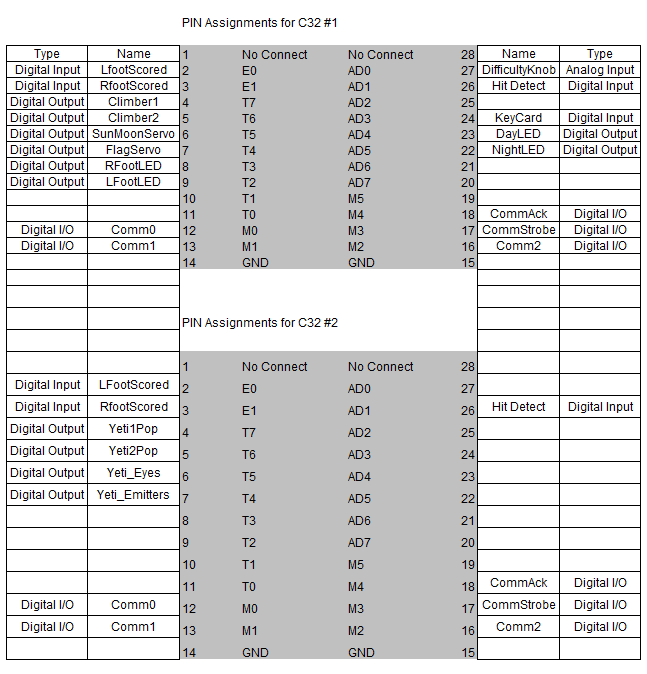
C32 Pin Assignments
C32 Communication Connections

C32 Input Pulldown Resistors

Integration of Electronic Modules

Side view of the arena with all circuit card assemblies installed.
